News
Research on the Wear Characteristics of the Hook Teeth of Cotton Pickers
Abstract
As a key core component of cotton pickers, the spindle is prone to wear of the hook teeth. This research explores the wear characteristics of the spindle hook teeth of cotton pickers under different working areas. The sampled spindles were cut, the element composition and hardness of the spindle hook tooth coating and substrate were determined, the surface morphology of the spindle hook tooth was characterized, and its wear area and coating thickness were extracted. Results show that the main constituent elements of the coating and substrate are Cr and Fe, respectively, the hardness of the coating is about 1020 HV0.1, and the hardness of the substrate is 470~840 HV0.1. During the field operation, scratches appeared on the surface of the coating, the coating thickness layer gradually decreased, and the coating peeled off as the operating area increased. Afterward, scratches and oxidized particles appeared on the surface of the substrate, the wear rate accelerated, and the wear area gradually increased. The wear of the spindle hook teeth started to appear from the front and rear tooth tips up to the tooth edge, the back of the tooth, and the doffering edge, hence forming a long boot-shaped wear area.
Keywords:
cotton picker spindle; hook tooth; wear area; coating thickness1. Introduction
As an important economic crop [1,2] and strategic material [3,4] in China, cotton is the main raw material of the textile industry and is widely used in the development of advanced functional materials and biomedical products [5]. Xinjiang has abundant sunshine, a dry climate, and large temperature differences in the summer, which are conducive to the growth and boll formation of cotton [6,7]. In 2021, the cotton output of Xinjiang reached 5.129 million tons [8], which accounted for 89.5% of the total output of China. Therefore, Xinjiang has become the main area of cotton production in the country. With the fast, convenient, and low labor intensity of mechanized cotton harvesting, cotton pickers are widely used in Xinjiang [9,10].
The spindle is the key core component of cotton pickers [11,12,13,14], whose performance directly determines the cotton picking quality and efficiency of cotton pickers [15,16,17,18]. The spindle is also the most consumed component of cotton pickers that is prone to wear and tear during field operations [19,20,21]. With the continuous domestic and foreign research on the wear failure of ingots, the present understanding of the wear mechanism of spindles has gradually become clear, and the wear failure of ingot picking is the result of the synergistic effect of multiple wear forms [22,23,24,25]. To analyze the change law of the wear profile of the hook tooth, previous studies have extracted the area and width of the wear area as evaluation indicators and found that the wear area increases exponentially and the wear width increases linearly along with the spindle industry [14,26,27]. Zhang Youqiang established a mechanical model of the spindle picking process to reveal the mechanism of spindle wear and failure [28]. However, the addition of load on spindle in this paper is too simple, and the complex working conditions of ingot picking field work are difficult to simulate. Luo Shuli characterized the micro-morphology of the hook teeth of spindle picking at different operation periods by SEM, built a friction mechanics model of the cotton doffing process, and found that the wear failure of the spindle hook teeth is mainly caused by abrasive wear [11]. However, Luo Shuli did not specify a method for obtaining spindle samples and ignored the influence of the spindle installation height on the wear failure of the spindle hook teeth. Gu Yanqing studied the ninth spindle in the middle of the front drum seat tube of cotton pickers under different working areas and characterized the wear morphology of the first hook tooth; they found that the wear of the spindle hook tooth coating is mainly caused by abrasive wear and fatigue spalling, whereas the wear of the substrate is the result of the combined action of abrasive wear and oxidative wear [26,27]. However, through further investigation, we found that in the actual operation process, the wear degree of the first to fifth spindles at the lower part of the spindle seat tube is greater than that of the spindles in the middle position. In sum, the present studies on the wear failure law of the hook teeth of the spindle and the reasons behind such failure are limited to a single hook tooth, whereas research on the wear failure of all hook teeth of the spindle is not comprehensive.
In this study, combined with the actual situation of spindle picking field operations, when the cotton picker reaches different operating areas, the spindle samples are obtained from the fixed position of the front drum seat tube. The 12 hook teeth of the spindle samples were then cut and sampled, the surface morphology of the hook teeth was characterized by scanning electron microscope), the coating and substrate elemental composition were characterized by energy spectrum analyzer, the hardness of the coating and substrate was tested using a microhardness tester, the coating thickness of the 12 hook teeth under different working areas was measured using a laser confocal microscope; the laws of coating peeling and coating thickness variation of 12 hook teeth were analyzed, and the causes of wear and failure of the hook teeth were explored. This study aims to analyze the wear and failure law of spindle hook teeth and to provide a reference for the optimization of the spindle hook teeth structure.
2. Materials and Methods
2.1. Test Materials and Equipment
2.1.1. Test Material
The material used in the test is a certain brand of spindle whose size parameters are shown in Figure 1a. The coating material of the spindle used in this study is Cr, and the substrate material is 20Cr.
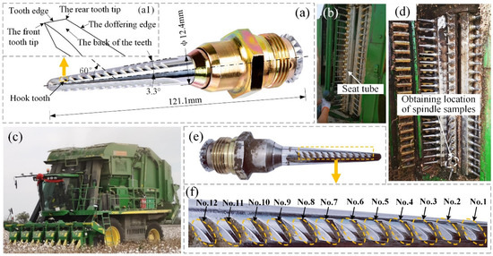
Figure 1. Installation and disassembly process of the spindle: (a) spindle assembly; (a1) hook tooth structure; (b) seat tube of the front drum; (c) field work process of the cotton picker; (d) obtaining the location of the spindle samples; (e) spindle sample; and (f) number of spindle hook teeth.
2.1.2. Test Equipment
The equipment used in the test is described in Table 1.
Table 1. Test equipment.

2.2. Field Working Conditions and Working Parameters of Cotton Pickers
A test was carried out from 30 September 2021 to 10 November 2021 between 8:00 am and 12:00 pm in the mechanical cotton picking fields of Kuitun City in Xinjiang. The ambient temperature and humidity during the operation and the operating parameters of the cotton picker are shown in Table 2.
Table 2. Ambient temperature, relative humidity, and working parameters of cotton pickers.
2.3. Installation and Disassembly of the Spindle
Spindle was installed in Kuitun, Xinjiang from 10:00 am to 1:00 pm in September 2021. The spindles purchased from the market (Figure 1a) were installed on the seat tube of the front drum of the cotton picker (Figure 1b). One seat tube had 20 spindle mounting positions with different heights. An investigation of the field operation process reveals that the spindles constantly touch the cotton stalks during their operation, and sandstorms are relatively frequent in Xinjiang, which leads the 1st to 3rd spindle being more prone to wear and failure. Therefore, when the working area of the cotton picker reached 150, 300, 450, and 600 hectares (the field operation process of the cotton picker is shown in Figure 1c), the second spindle on the front drum seat tube was disassembled as a sample, and three spindle samples were obtained at each time. These samples were placed in bags, marked, and sealed for storage. The acquisition position of these samples is shown in Figure 1d, the obtained spindle sample is shown in Figure 1e, and the worn area is shown in Figure 1f. The 12 hook teeth of the spindle sample are numbered as shown in Figure 1f.
2.4. Cutting and Sampling of Spindles
The spindle samples were cut using a CNC wire EDM machine. The path of the first cutting and the spindle clamping method are shown in Figure 2a, and a row of hook teeth of the spindle (as shown in Figure 2b) was obtained. To facilitate the SEM characterization of the surface of the hook teeth, a second cut was performed on a row of hook teeth. The path of the second cutting and the spindle clamping method are shown in Figure 2c. The cut samples were ultrasonically cleaned (as shown in Figure 2d) and were air dried to obtain the surface samples of hook teeth. The third cutting was performed on the spindle sample (as shown in Figure 2f) after the first cutting. The cutting path and spindle clamping method are shown in Figure 2g. A metallographic specimen mounting machine was used to inlay the cut samples that were obtained after the third cutting (as shown in Figure 2h). The mosaic process is shown in Figure 2i. The mosaic sample (as shown in Figure 2j) was ground and polished with a metallographic grinding and polishing machine. The grinding and polishing processes are illustrated in Figure 2k, and a sample of the hook tooth section was obtained (as shown in Figure 2l). The material of the sandpaper used in the grinding process is SiC, and the particle sizes are 800#, 1200#, and 2000#, respectively. Repeat the above operation to obtain 3 sets of hook tooth surface samples and cross-section samples, respectively.
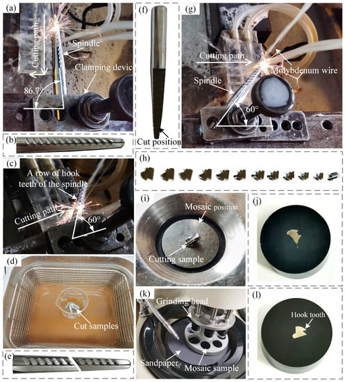
Figure 2. Cutting and sample preparation process: (a) first wire cutting process; (b) row of hook teeth of the spindle; (c) second wire cutting process; (d) ultrasonic cleaning process; (e) surface samples of the hook teeth; (f) spindle sample after the first cutting; (g) third wire cutting process; (h) cut samples; (i) mosaic process; (j) mosaic sample; (k) grinding and polishing processes; and (l) cross-section samples of the hook teeth.
2.5. Sample Testing Process
A scanning electron microscope was used to characterize the microstructure of the surface of the hook teeth at an acceleration voltage of 15 kV, an energy spectrum analyzer was used to measure the element composition and content in the spindle hook tooth coating and substrate at an accelerating voltage of 16 kV, and a microhardness tester was used to test the hardness of the hook tooth section samples along the direction from the coating to the substrate with a test load of 0.1 kg and holding time of 15 s. The coating thickness of the hook teeth of the spindle was extracted via laser Confocal Microscope.
3. Results and Discussion
3.1. Composition and Hardness of the Coating and Substrate
According to the literature [27], the phase structures of the substrate and coating are face-centered cubic structure and body-centered cubic structure, respectively. In this study, the composition and hardness of the substrate and coating were tested.
Figure 3a,a1 present the results of an EDS (Energy Dispersive Spectrum) analysis of the coating and the corresponding scanning area, whereas Figure 3b,b1 show the EDS analysis of the substrate and the corresponding scanning area, respectively. The main component of the coating is Cr, whereas the main element of the matrix is Fe.
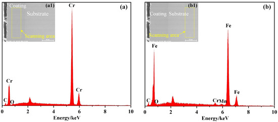
Figure 3. EDS analysis of the coating and substrate: (a) EDS analysis of the coating; (a1) scanning area of the coating; (b) EDS analysis of the substrate; and (b1) scanning area of the substrate.
Figure 4a shows the process of testing the coating and substrate hardness, whereas Figure 4b shows the test area. The test was performed from the coating to the substrate (as shown in Figure 4c). The hardness change curve from the coating to the substrate in Figure 4d reveals that the hardness of the coating is about 1020 HV0.1, whereas that of the substrate near the coating is about 840 HV0.1. The hardness of the substrate decreases along with increasing measurement distance, and the final storage is stable at about 470 HV0.1 due to the heat treatment of the spindle surface before electroplating. In addition, the hardness gradually decreases along with the increasing depth of heat treatment [27]. Figure 4e–g shows the indentation from the coating to the substrate hardness test.
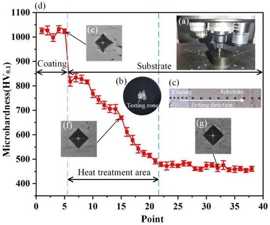
Figure 4. Coating and substrate hardness testing: (a) first wire cutting process; (b) testing zone; (c) testing direction; (d) coating to substrate hardness change curve; (e) coating hardness test indentation; (f) heat treatment area hardness test indentation; and (g) substrate hardness test indentation.
3.2. Surface Topography of Hook Teeth under Different Working Areas
3.2.1. Surface Microstructure of Hook Teeth of the New Spindle
Figure 5a presents a micrograph of the hook tooth of the new spindle, whereas Figure 5(a1) presents a partial micrograph of the hook tooth mark. Some defects, such as microcracks, pocking marks, and pits, can be observed on the surface of the hook teeth of the new ingot picking. The analysis results show that the microcracks on the surface of the hook teeth are caused by the internal stress generated during the machining and electroplating process of the spindle machine [29,30,31], the holes are caused by the hydrogen evolution from the cathode staying on the surface of the spindle during the electroplating process [32], and the pocking marks and pits are caused by the uneven surface of the spindle prior to electroplating [33].
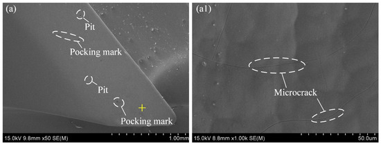
Figure 5. Surface morphology of new spindle hook teeth: (a) general micrograph of the hook teeth; and (a1) local micrograph of the hook teeth.
3.2.2. Surface Microstructure of The Hook Teeth of the Spindle in a 150-Hectare Operation
When the working area of the cotton picker reaches 150 hectares, the coating peels off at the front and rear tips of hook teeth nos. 1 to 3, whereas hook teeth nos. 4 to 12 show no obvious wear. Figure 6a–c presents the scanning electron microscope (SEM) images of the wear morphology of hook teeth nos. 1 to 3 when the cotton picker has an operating area of 150 hectares, whereas Figure 6(a1) presents a partial micrograph of the hook tooth nos. 1 mark. Compared with the new spindle, when the working area reaches 150 hectares, scratches and greater pits can be found on the surface of the hook teeth.
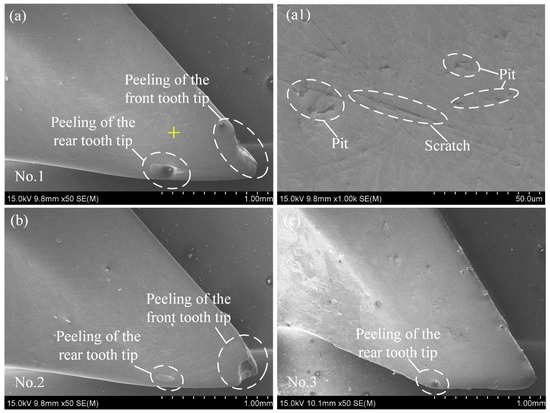
Figure 6. Wear morphology of hook teeth nos. 1 to 3 in a 150-hectare operation: (a–c) Wear morphology of hook teeth nos. 1 to 3; and (a1) partial micrograph of the hook tooth nos. 1 mark.
3.2.3. Surface Microstructure of the Hook Teeth of the Spindle in a 300-Hectare Operation
When the operating area reaches 300 hectares, the wear of hook teeth nos. 1 to 3 is aggravated, and the coating peels off at the tooth edge. Meanwhile, hook teeth nos. 4 to 8 show different degrees of wear on their front and rear tips, whereas hook teeth nos. 9 to 12 show no obvious wear. Figure 7a–h presents the SEM images of the wear morphology of hook teeth nos. 1 to 8 when the cotton picker has an operating area of 300 hectares. Figure 7(a1) presents a partial micrograph of the hook tooth no. 1 mark. When the operating area of the cotton picker reaches 300 hectares, many dense scratches can be observed on the hook tooth surface.
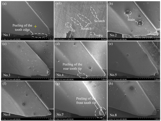
Figure 7. Wear morphology of hook teeth nos. 1 to 8 in a 300-hectare operation: (a–h) Wear morphology of hook teeth nos. 1 to 8; and (a1) partial micrograph of the hook tooth nos. 1 mark.
3.2.4. Surface Microstructure of the Hook Teeth of the Spindle in a 450-Hectare Operation
When the operating area reaches 450 hectares, the wear degree of hook teeth nos. 1 to 3 increases, and the wear area extends to their back and the doffering edge, thereby forming a boot-like profile. Meanwhile, the blades of hook teeth nos. 4 to 6 show partial wear, the front and rear tips of hook teeth nos. 7 and 8 show relatively slight wear, and hook teeth nos. 9 to 12 show no obvious wear. Figure 8a–h presents SEM images of the wear morphology of hook teeth nos. 1 to 8 when the cotton picker operates for 450 hectares. The partial micrograph of the hook tooth nos. 1 mark in Figure 8(a1) shows that the coating peels off in the marked area and that scratches and a small amount of oxide particles appear on the exposed substrate. Figure 9a,b shows the EDS analysis of the oxide particles and the corresponding scanning area, respectively. EDS analysis shows that the main components of the oxide particles are O and Fe.
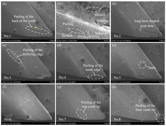
Figure 8. Wear morphology of hook teeth nos. 1 to 8 in a 450-hectare operation: (a–h) Wear morphology of hook teeth nos. 1 to 8; and (a1) partial micrograph of the hook tooth nos. 1 mark.
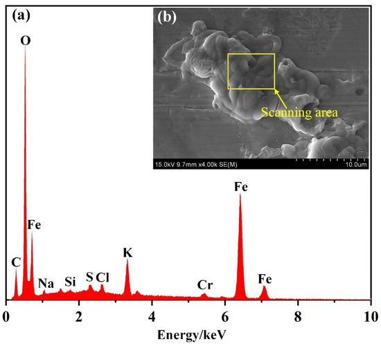
Figure 9. (a) EDS analysis of the oxide particles; and (b) scanning area.
The analysis results indicate that the scratches on the coating and substrate are caused by the continuous contact of the spindle with sand, cotton stalks, bell shells, and other hard substances during the field operation, which usually leads to abrasive wear [34,35,36]. The peeling of the coating is caused by the periodic contact surface of the hook teeth of the spindle with cotton stalks, bell shells, and sand grains during operation, thereby resulting in reduced life and fatigue spalling, which are indicative of fatigue wear [37,38,39]. An investigation of the field operation process of cotton pickers reveals that the humidity in Xinjiang is relatively high in the morning and evening, and a large number of dewdrops will condense on the cotton surface in the early morning, hence providing conditions for the oxidation reaction of the substrate, which is a phenomenon of oxidative wear [40,41].
3.2.5. Surface Microstructure of the Hook Teeth of the Spindle in a 600-Hectare Operation
When the operating area reaches 600 hectares, hook teeth nos. 1 to 11 all wear to varying degrees, hook teeth nos. 1 to 5 are seriously worn and a large area of coating on their back peels off, the edge and doffer edge of hook teeth nos. 6 to 8 are worn, hook teeth nos. 1 to 8 form a long boot-shaped wear area, hook teeth nos. 9 to 11 show a slight wear on their front and rear tips, and hook tooth nos. 12 shows no obvious wear. Figure 10a–k presents SEM images of the wear morphology of hook teeth nos. 1 to 11 when the cotton picker operates for 600 hectares. The partial micrograph of the hook tooth no. 1 mark in Figure 10(a1) shows that when the working area reaches 600 hectares, the coating in this area is completely peeled off, a large number of scratches and a small amount of oxide particles appear on the exposed substrate, and the width of the scratches increases.
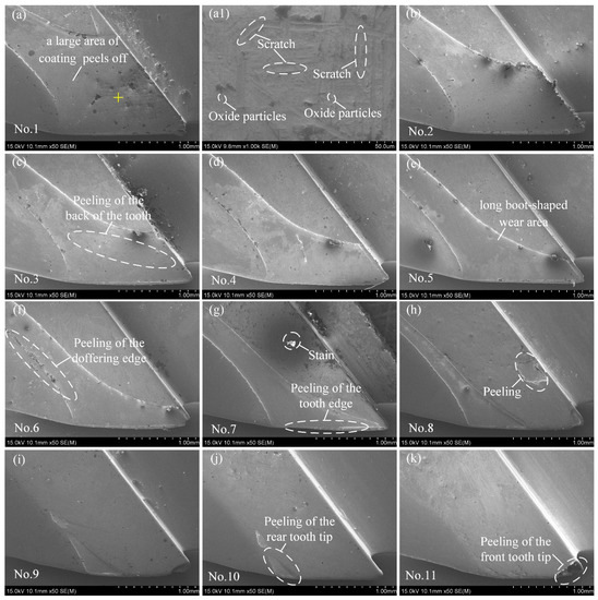
Figure 10. Wear morphology of hook teeth nos. 1 to 11 in a 600-hectare operation: (a–k) Wear morphology of hook teeth nos. 1 to 11; and (a1) partial micrograph of the hook tooth nos. 1 mark.
In sum, the wear of the spindle hook teeth starts from their front and rear tips before extending to their edges and back and then extending backward along the doffering edge to form a long boot-shaped wear area. Compared with hook teeth nos. 7 to 12, nos. 1 to 6 are more easily worn. The analysis results reveal that in the process of picking cotton, the hook teeth insert themselves into the cotton to hook the material, and given that the front and rear tooth tips are relatively sharp and the stress is concentrated, the front and rear tooth tips tend to be the first to wear out. In the process of picking cotton, the hook teeth are constantly in contact with cotton fibers, cotton rods, and bell shells, and the coating on the edges and back of the teeth is prone to abrasive wear and even fatigue peeling [24]. During the doffing process of the spindle, the rear tooth tips and the doffering edge are prone to wear under the extrusion action of the doffer disc, and the coating will peel off at the later stage [11]. Under this situation, hook teeth nos. 1 to 6 are more likely to be worn because they are mainly used to complete the winding of cotton in the spindle process [42].
3.3. Wear Area of All Hook Teeth under Different Working Areas
To intuitively reflect the wear and failure law of hook teeth nos. 1 to 12 of the spindle, the image processing method was used to extract the wear area of these teeth across different stages to quantify their wear degree. Figure 11a shows the wear area of the hook teeth of the spindle after the cotton picker operates in a certain area, whereas Figure 11b shows the change curve of the wear area of hook teeth nos. 1 to 12 under different working areas. Across different operation stages, the wear area of hook teeth nos. 1 to 12 ingot picking shows a downward trend. As the working area increases, the wear area of the hook teeth of the spindle gradually increases, and the growth rate of the wear area increases; meanwhile, the wear area of hook teeth nos. 1 to 6 increases faster than that of hook teeth nos. 7 to 12. Figure 10 shows that when the operating area reaches 600 hectares, the wear area of hook teeth nos. 1 to 6 reaches 1.5 mm2, and a large area of the coating peels off. The substrate that loses the protection of the coating is quickly worn out, the hook teeth lose their original structure, their cotton picking ability is reduced, and the spindle fails. At this time, the wear of hook teeth nos. 7 to 12 is relatively slight, and the wear failure of the spindle can be ascribed to the serious wear of hook teeth nos. 1 to 6.
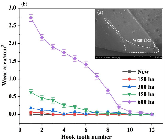
Figure 11. Wear area testing: (a) wear area; and (b) change curve of the wear area.
3.4. Coating Thickness of All Hook Teeth under Different Working Areas
To explore the wear of hook teeth nos. 1 to 12 across different operation stages, the coating thickness of the hook teeth was selected as an index to quantify the wear degree of the hook teeth of the spindle. The coating thickness was extracted using a confocal microscope, and the coating thickness testing process is shown in Figure 12a. As shown in Figure 12b, the test position is located about 500 μm away from the tooth edge. Figure 12c presents a micrograph of the test area, and Figure 13 shows the variation curve of the coating thickness of hook teeth nos. 1 to 12 under different working areas. As can be seen from Figure 12, the thickness of the coating on the hook teeth of the new spindle decreases as the number of the hook teeth increases. With the increasing working area, the thickness of all 12 hook teeth gradually decreases. The coating of hook teeth nos. 1 to 6 wears faster than those of hook teeth nos. 7 to 12. When the spindle picking operation area reaches 450 hectares, the thickness of the spindle hook tooth coating increases along with the hook tooth number, and the coating of the hook tooth nos. 1 measurement area peels off. Meanwhile, when the operation area reaches 600 hectares, the coating of hook teeth nos. 1 to 5 measurement area peels off. The analysis reveals that the coating thickness of the hook teeth of the new spindle decreases along with the increasing number of hook teeth because the hook tooth part of the spindle is conical with a small front end and a large rear end, and the front end charge is relatively concentrated during the electroplating process. The wear rate of hook teeth nos. 1 to 6 is higher than that of hook teeth nos. 7 to 12 because the process of picking cotton by spindle mainly completes the hooking of cotton fibers through hook teeth nos. 1 to 6 [42].
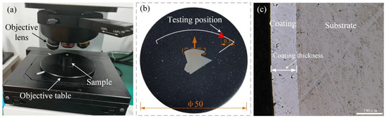
Figure 12. Coating thickness testing: (a) testing procedure; (b) testing position; and (c) micrograph of the test area.
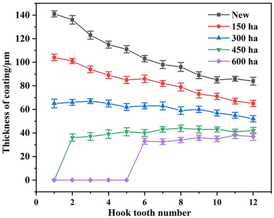
Figure 13. Coating thickness change curve.
4. Conclusions
- The main constituent elements of the coating and substrate are Cr and Fe, respectively. The hardness of the coating is about 1020 HV0.1, whereas that of the substrate near the coating is about 840 HV0.1. The hardness of the substrate decreases along with the increasing heat treatment depth before becoming stable at about 470 HV0.1.
- The coating surface of the new spindle hook teeth has some structural defects, such as microcracks, pocking marks, and pits. During the field operation, scratches appeared on the surface of the hook tooth coating, and the coating peeled off as the operating area increased. Afterward, scratches and oxidized particles appeared on the surface of the substrate, and the wear rate accelerated. The wear of the spindle hook teeth started to appear from the front and rear tooth tips up to the tooth edge, the back of the tooth, and the doffering edge, hence forming a long boot-shaped wear area.
- Across different operation stages, the wear area of the hook teeth nos. 1 to 12 shows a downward trend. As the working area increases, the wear area of the hook teeth gradually increases, and the rate of such increase also rises.
- The thickness of the new hook tooth coating decreases along with the increasing hook tooth number. As the working area increases, the thickness of the 12 hook teeth coating gradually decreases.
- I have the following suggested points for reducing hook tooth wear: first, increase the thickness of the coating; second, add nanoparticles to the coating to enhance the wear resistance of the coating; third, optimize the hook tooth angle parameter; finally, passivate the tooth tip of the hook tooth.
Author Contributions
Conceptualization, H.L., H.Z. and X.F.; methodology, H.Z., X.F., H.W. and H.L.; software, H.L., Y.T. and J.L.; validation, H.Z. and X.F.; formal analysis, Y.G. and H.L.; investigation, H.L., Y.G., X.D., Y.T. and J.L.; resources, H.Z. and H.W.; data curation, H.L., H.Z. and X.F.; writing—original draft preparation, H.L. and H.Z.; writing—review and editing, H.Z., X.F. and X.D.; visualization, H.L. and H.Z.; supervision, H.Z. and X.F.; project administration, H.Z. and X.F.; funding acquisition, H.L., H.Z., H.W. and X.F. All authors have read and agreed to the published version of the manuscript.
Funding
This work was financially supported by the Innovation and Development Project of the Shihezi University (Grant number: CXFZ202015), the Corps Major Scientific and Technological Projects (Grant number: 2018AA008), the Fundamental Research Funds for the Central Universities (Grant number: KYLH2022002), the Jiangsu Agricultural Science and Technology Innovation Fund (Grant number: CX (20) 3085).
Institutional Review Board Statement
Not applicable.
Informed Consent Statement
Not applicable.
Data Availability Statement
All relevant data presented in the article are stored according to institutional requirements and, as such, are not available online. However, all data used in this manuscript can be made available upon request to the authors.
Conflicts of Interest
The authors declare no conflict of interest.
References
- Fue, K.G.; Barnes, E.M.; Porter, W.M.; Rains, G.C. Visual Control of Cotton-picking Rover and Manipulator using a ROS-independent Finite State Machine. In Proceedings of the 2019 Beltwide Cotton Conferences, New Orleans, LA, USA, 8–10 January 2019. [Google Scholar]
- Niu, G.L.; Li, B.; Liu, Y.; Li, Y.X.; Wang, T.; Wang, S.G. Development and research status of cotton picker in China. J. Chin. Agric. Mech. 2020, 41, 212–218. [Google Scholar]
- Chen, X.G.; Zhang, H.W.; Wang, L.; Zhang, L.C.; Wang, J.; Li, J.X.; Gu, Y.Q. Optimization and experiment of picking head transmission system of horizontal spindle type cotton picker. Trans. Chin. Soc. Agric. Eng. 2020, 36, 18–26. [Google Scholar]
- Li, T.; Hao, F.P.; Han, Z.D.; Fang, X.F.; Han, K.; Li, X.D. Theoretical Analysis and Experiment of Picking Cotton with Horizontal Spindle. Trans. Chin. Soc. Agric. Mach. 2018, 49, 233–238. [Google Scholar]
- Hosseinali, F.; Thomasson, J.A. Variability of fiber friction among cotton varieties: Influence of salient fiber physical metrics. Tribol. Int. 2018, 127, 433–445. [Google Scholar] [CrossRef]
- Gu, Y.W. Analysis of climatic conditions for cotton growth in Xinjiang. Mod. Agric. Sci. Technol. 2016, 2, 255. [Google Scholar]
- Zhang, D.W. Analysis of climatic conditions for cotton planting in Hutubi County, Xinjiang. Beijing Agric. 2015, 31, 133–134. [Google Scholar]
- Announcement of the National Bureau of Statistics on Cotton Output in 2021. Available online: http://www.stats.gov.cn (accessed on 20 April 2022).
- Rizaev, A.; Matchanov, R.; Yuldashev, A.T.; Kuldashev, D.A.; Djuraeva, N.B.; Karimov, N.; Ashurov, N. Cotton harvesters for one-time cotton-picking. Mater. Sci. Eng. 2021, 1030, 012173. [Google Scholar] [CrossRef]
- Wu, J.S.; Chen, X.G. Present situation, problems and countermeasures of cotton production mechanization development in Xinjiang Production and Construction Corps. Trans. Chin. Soc. Agric. Eng. 2015, 31, 5–10. [Google Scholar]
- Luo, S.L.; Zhang, Y.Q.; Ma, S.H. Wear Mechanism Analysis on Spindle of Cotton Picker. J. Tarim Univ. 2018, 30, 132–137. [Google Scholar]
- Wu, B.; Zhang, L.X.; Zuo, Y.T.; Wei, M. Research of Material Elements Distribution in Cotton Picker’s Level Spindle Based on SEM and EDS. J. Agric. Mech. Res. 2013, 35, 174–178. [Google Scholar]
- Wu, T.S.; Hu, R.; Lu, Y.Z. Research on the Digital Image Processing Method for Spindle Wear Degree of Cotton Picker. Mech. Res. Appl. 2017, 30, 159–162. [Google Scholar]
- Li, W.C.; Qiao, Y.Y.; Deng, Y.M.; Liu, X.M.; Zhang, H.W. Evaluation and analysis of hook tooth wear for cotton picker spindle. J. Chin. Agric. Mech. 2018, 39, 11–14. [Google Scholar]
- Baker, K.D.; Delhom, C.D.; Hughs, E. Spindle diameter effects for cotton pickers. Trans. ASABE 2017, 33, 321–327. [Google Scholar] [CrossRef]
- Baker, K.D.; Hughs, E.; Foulk, J. Cotton quality as affected by changes in spindle speed. Trans. ASABE 2010, 26, 363–369. [Google Scholar]
- Baker, K.D.; Hughs, E.; Foulk, J. Spindle speed optimization for cotton pickers. Trans. ASABE 2015, 31, 217–225. [Google Scholar]
- Meng, F.M.; Chen, N.W.; Chen, Z.W. Hard chromium coating effects on tribological performances for nonlubricated and lubricated spindle of cotton picker. Proc. Inst. Mech. Eng. Part L J. Mater. Des. Appl. 2016, 230, 446–453. [Google Scholar] [CrossRef]
- Wu, T.S.; Hu, R.; Lu, Y.Z. Automatic Inspection of Cotton picking spindle and its life prediction. Machinery 2018, 45, 32–37. [Google Scholar]
- Zhang, Y.Q.; Cai, Z.P.; Tian, Y.; Meng, Y.G. Improvement of mechanical properties and wear resistance of cotton picker spindle by electromagnetic treatment. Trans. Chin. Soc. Agric. Eng. 2018, 34, 3–37. [Google Scholar]
- Meng, F.; Chen, Y.; Yang, Y.; Chen, Z. Friction and wear behavior of electroless nick coating used for spindle of cotton picker. Ind. Lubr. Tribol. 2016, 68, 220–226. [Google Scholar] [CrossRef]
- Wu, B. The Analysis of Cotton-Picker Level Spindle′s Material and Heat Treatment Process; Shihezi University: Shihez, China, 2013. [Google Scholar]
- Amuti, G. Since the Material Analysis and Optimization of Key Parts of Cotton Picker; Xinjiang University: Urumqi, China, 2014. [Google Scholar]
- Deng, Y.M.; Li, W.C.; Yu, T.Z.; Wang, C.H.; Xu, J.T.; Qiao, Y.Y. Analysis and study on spindle component wear factors of horizontal cotton picker. Joumal Chin. Agric. Mech. 2017, 38, 11–13. [Google Scholar]
- Zhang, Y.Q.; Li, Y.; Meng, Y.Q. Wear Behavior of Spindles of Cotton Picker in Field Work. J. Tribol. 2021, 143, 021703. [Google Scholar] [CrossRef]
- Gu, Y.Q.; Zhang, H.W.; Fu, X.Q.; Wang, L.; Shen, Z.Y.; Wang, J.; Song, Z.; Zhang, L.C. Experimental Wear Behavior Analysis of Coated Spindle Hook Teeth under Real Harvesting Work Conditions. Materials 2021, 14, 2487. [Google Scholar] [CrossRef] [PubMed]
- Gu, Y.Q.; Zhang, H.W.; Fu, X.Q.; Wang, L.; Wang, J.; Cai, Y.X.; Li, H.Y. Comparative Analysis of the Wear Performance of Spindle Hook Teeth During Fieldwork. J. Tribol. 2022, 144, 011706. [Google Scholar] [CrossRef]
- Zhang, Y.Q.; Wang, W.; Liao, J.A. Wear failure analysis on spindle of cotton picker. Trans. Chin. Soc. Agric. Eng. 2017, 33, 45–50. [Google Scholar]
- Pina, J.; Dias, A.; Francois, M.; Lebrun, J.L. Residual stresses and crystallographic texture in hard-chromium electroplated coatings. Surf. Coat. Technol. 1997, 96, 148–162. [Google Scholar] [CrossRef]
- Lee, S.L.; Capsimalis, G.P. Elastic anisotrophy and residual stress in textured production electrolytic chromium coatings on steel. Adv. X-Ray Anal. 1997, 39, 257–266. [Google Scholar]
- Weiss, B.; Lefebvre, A.; Sinot, O.; Marquer, M.; Tidu, A. Effect of grinding on the sub-surface and surface of electrodeposited chromium and steel substrate. Surf. Coat. Technol. 2015, 272, 165–175. [Google Scholar] [CrossRef]
- Ellina, L.; Nikiforow, K.; Wierzchon, T.; Ulbin-Pokorska, I. Effect of plasma nitriding on hydrogen behavior in electroplated chromium coating. Surf. Coat. Technol. 2001, 145, 139–145. [Google Scholar]
- Zhang, Y.H. Discussion on pitting and pinhole problems in hard chromium plating. Electroplat. Pollut. Control. 2009, 29, 42–43. [Google Scholar]
- Kešner, A.; Chotëborský, R.; Linda, M. The Effect of Microstructure on Abrasive Wear of Steel. In Proceedings of the 1st Nommensen International Conference on Technology and Engineering, Medan, Indonesia, 11–12 July 2017. [Google Scholar]
- Yang, C.J.; Huang, X.P.; Wu, J.F.; Wan, F.X. Friction and Wear Behavior of 45# Steel with Different Plant Abrasive. In Advanced Materials Research; Trans Tech Publications Ltd.: Freienbach, Switzerland, 2013; Volume 712, pp. 74–77. [Google Scholar]
- Purkayastha, S.; Dwivedi, D.K. Abrasive and erosive wear performance of rare earth oxide doped Ni/WC coatings. J. Tribol. 2014, 136, 011602. [Google Scholar] [CrossRef]
- Korzynski, M.; Dzierwa, A.; Pacana, A.; Cwanek, J. Fatigue strength of chromium coated elements and possibility of its improvement with ball peening. Surf. Coat. Technol. 2009, 204, 615–620. [Google Scholar] [CrossRef]
- Dzierwa, A.; Pawlus, P.; Reizer, R. Surface Topography of Chromium Coatings after Pneumatic Ball Peening. Key Eng. Mater. 2008, 381–382, 113–116. [Google Scholar] [CrossRef]
- Korzynski, M.; Pacana, A.; Cwanek, J. Fatigue strength of chromium coated elements and possibility of its improvement with slide diamond burnishing. Surf. Coat. Technol. 2009, 203, 1670–1676. [Google Scholar] [CrossRef]
- Stott, F.H. The role of oxidation in the wear of alloys. Tribol. Int. 1998, 31, 61–71. [Google Scholar] [CrossRef]
- Yang, Y.; Liu, Y.K.; Wang, F.; Li, L.; Chen, J.J.; Yang, G.C.; Li, B.R.; Zheng, J. Corrosive Wear Behavior of NiCoCrAlY/NiCoCrAlYN Coatings. Surf. Technol. 2022, 51, 284–294. [Google Scholar]
- Bi, X.S. The Study on Work Mechanism of Cotton Picker Level Ingots; Shihezi University: Shihezi, China, 2007.
Categories
News
Contact Us
Contact: Agriculture Machinery Parts
Phone: 86(0)15869109368
Tel: 86-571-89967020
E-mail: dawopu@gmail.com
Add: Hangzhou City Zhejiang Province China